Display Panel Device Driver
In this lab, you will extend the
Virtual LED Display Panel
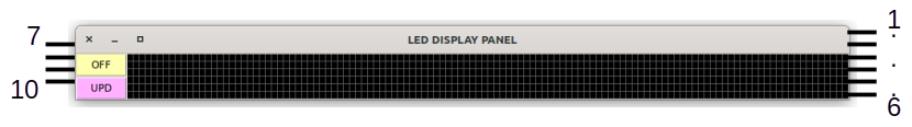
LED Panel has 10 virtual pins
- Pins 1 to 6 set the colour of the display.
Pins 1, 2 set the red colour in four levels
Pins 3, 4 set the green colour in four levels
Pins 5, 6 set the blue colour in four levels - Pins 7, 8 control the speed of the display in four speeds
- Pin 9 controls the direction of movement: 0 for R-L and 1 for L-R
- Pin 10 indicates if the message has changed and needs updating the display
The device also has
Device Driver
The device driver for the Virtual LED Panel (VLED Panel) follows the same lines as the memory driver done in class. While the earlier driver used only 1 byte of storage, the current driver needs 80 bytes. Name this device driver
- Write the driver functions
panel_init() panel_release() panel_open() panel_close() panel_read() panel_write()
- Link these functions correctly to the Linux kernel interfaces
as discussed in the class using the
file_operations structure.
Compiling and Creating the Device Driver
Follow the steps below to compile your device driver. Once you get it compiled without any errors, please call your TAs or the instructor for testing your device driver.- Open a
new terminal . - Login to your file server by typing
ssh -X 10.5.0.90 - List the devices in the
/dev directory and find a suitablemajor number for theVLED_Panel device. - Set the device
major number correctly in your device driver code. - Download this Makefile;
edit the first line to your device driver file name and compile
your code typing
make . Make sure there are no errors and that a.ko file has been created.
Do the following once you are given a terminal in which you have
- Create the device interface in the same directory as your code using
mknod command. Note that this is different from what was done in the class. We are NOT creating the device in/dev directory. - Change the device permissions and make it writable for all users.
- Test your device driver by doing the following
insmod <your .ko file name> cat > <your device file name>
Hello, World!
^dmore <your device file name>
Hello, World! displayed on the screen.
If you don't see it, there is an error in your device driver or the device file name. Check everything, if necessary go back to your computer, edit and recompile your source code and try again.
Testing the Device Driver
Do the following to test the device driver.
- Launch the VLED Panel device by typing
python3 led_panel.py <device file name> & - Set the VLED Panel to display messages in MAGENTA colour, (i.e. bright Red + bright Blue), at a speed of 2 and from Right-to-Left. Write this data into the device before going to the next step.
- Turn the device ON. You will not see anything right now.
- Write the Message
Lab - V from 6 Nov 2025 into the device. - Display the Message on the VLED Panel by turning the panel OFF and then ON again..
You are free to try the different options and messages to see how long a message may be displayed or any other tests you can think of.